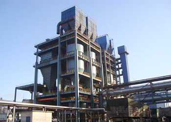


Φ6000 balling disc is used for pelletizing of iron ore fines. As one of main support equipment for various pellet plants, the equipment has strong adaptability, its inclination angle and rotation speed are adjustable, and the equipment adopts electric rotary scraper.
Φ6000 balling disc is used for pelletizing of iron ore fines. As one of main support equipment for various pellet plants, the equipment has strong adaptability, its inclination angle and rotation speed are adjustable, and the equipment adopts electric rotary scraper.
Manufacturing specifications
(1)The manufacture and installation of balling disc shall be carried out strictly according to the drawings and must conform to the provisions in this document;
(2)The material of all components shall have manufacturer’s certificate of qualification. Otherwise, it shall be used only after having passed qualification test. It’s allowed to use alternative material with mechanical performance no lower than that in this design. But for important component, the alternative material can be used only after approval by manufacturer’s technical inspection department and design unit;
(3)The welding of metal component shall accord with the related provisions in JB/ZQ400.3-86. The dirt shall be removed from the surface of all weldments before welding. The weld joint shall be tight and even without such defect as irregularity, scar, crack, slag inclusion and incomplete penetration. If the total area of various weld defects exceed 10% of weld cross section, rewelding is necessary;
(4)The castings shall conform to the related provisions in JB/ZQ4000.5-86 General Technical Requirements of Castings;
(5)The forging for the blank of shaft parts shall conform to the related provisions in JB/ZQ4000.7-86 General Technical Requirements of Forgings.
Assembly specifications
(1)The assembling of this equipment shall be carried out according to the provisions in JB/ZQ4000.9-86《 General Technical Requirements of Assembling》
(2)After manufacturing, this equipment must be checked and accepted by manufacturer’s technical inspection department and provided with supporting document as required by this document before its delivery.
-
Base
Because load is applied on this equipment during operation, the installation quality of base frame foundation is demanding. The base frame and foundation shall have good contact to ensure smooth running of equipment. The installation height and permissible position error are as follows:

-
Drive part
Main shaft installation: Fit front bearing onto main shaft, and place the main shaft in spindle box by use of lifting bolt. Then install rear bearing into the spindle box, and use lock nut to tighten taper sleeve. Finally put thrust bearing into end cap, and use bolt to fasten the end cap on the spindle box.
Support installation: After assembling, long shaft (YJ60.02.05), short shaft (YJ60.02.15) and their bearings (60.02.04) and spindle box (YJ60.01.01) shall be hoisted and installed on the base. After assignment, use taper pins for positioning and then tighten bolts.
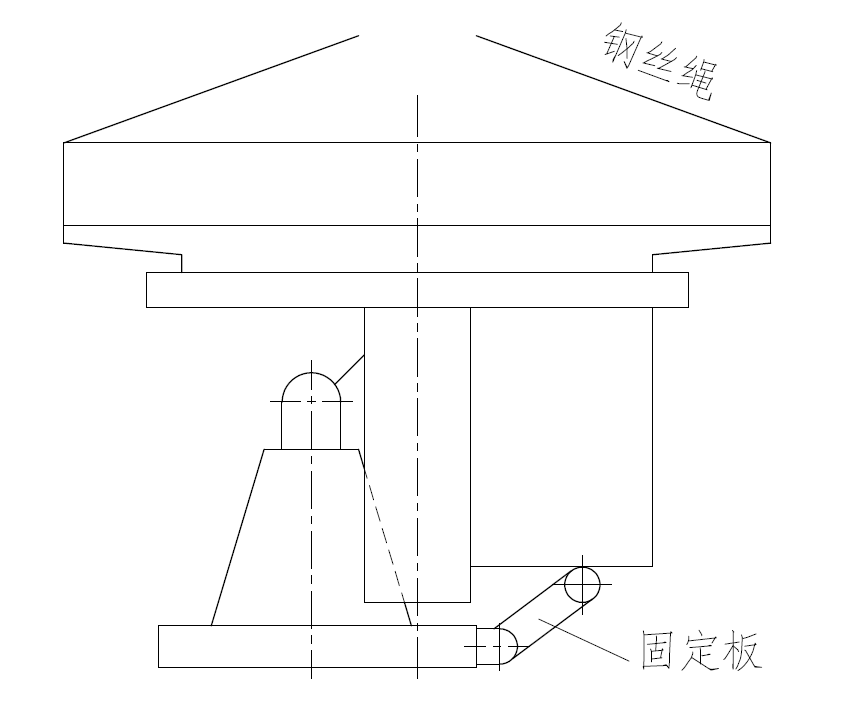
Disc installation: Connect main gear (307.03 spare 01.13) and middle disc (307.03 spare 01.15) together by bolt. Check and confirm that nothing is loose. Use lifting hook to hoist this component horizontally, and at this time the main shaft shall be placed perpendicular to the ground. Use fixing plate to fasten the spindle box on base frame (as shown in the figure below), and fit disc hub onto the main shaft, and then connect the disc and main shaft by bolt and gland. Install side bracket and side disc, and use pins for positioning and tighten bolts after geometric tolerance has met the requirement. Tighten the bolts again after load running for 200 hours.
-
Inclination adjusting device
Hoist the disc by use of lifting hook and steel wire rope, and then remove the fixing plate and get prepared for installation of inclination adjusting device. Check if connected steel plate has enough strength and make adjustment. And check if the hinge mount connected with adjusting device is loose, if weld joint is tight and even and if the location of upper and lower hinge mount meets requirement. Install adjusting device only after all these are qualified.
-
Support & beam
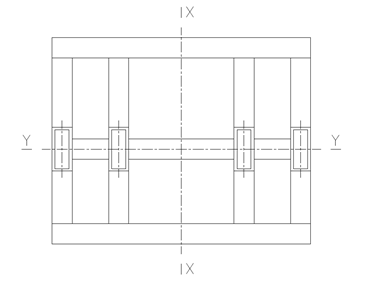
Install support I (YJ60.02.02) at both sides of long shaft and short shaft and fasten the shafts to the support by use of pin. Tighten hand wheel (YJ60.02.07)and then install support II (YJ60.02.06). The geometric tolerance shall meet requirements in the figure.
-
Scraper system
Complete the assembling of scraper and ensure flexible rotation of shaft. Then install the scraper entirely on the beam and adjust the position of tool bit, which shall be 30mm away from disc surface. Installation location tolerance shall meet the requirements in the figure.
-
Motor and reducer
After installing the motor and reducer, check the degree of tension for V-belt and make sure that it is neither too tight nor too loose.
-
Other accessories
Including gear cover, inspecting stand, lubricating pipeline and etc.. Careful and comprehensive inspection shall be carried out on the equipment by reference to the drawing and this manual, including the tightness of each bolt, if mounting position of each component is correct, and if there exists interference phenomenon during hand turning. And careful check shall be made on lubricating device and its pipeline system to ensure unblocked oil circuit at various lubricating points.
Equipment Performance Parameters
|
Main Parameters: |
|
|
Disc diameter |
Φ6000mm |
|
Disc edge height |
650mm |
|
Disc inclination adjusting device |
43-53° |
|
Disc speed |
3.55-8.5r/min |
|
Throughput |
40t/h |
|
Motor: |
|
|
Main motor model |
YVF2-315 S-4
|
|
Rated power |
110kw |
|
Rated speed |
1500 r/min |
|
Reducer: |
|
|
Model |
NGW-QF112A I=25 |
|
Speed ratio |
25 |
|
Narrow V-belt: |
|
|
Model |
SPB3550 5V1400 6nos. |
|
Open gear: |
|
|
Modulus |
22 |
|
Gear ratio |
6.85 |
|
Open gear: |
|
|
Number of large gear teeth |
137 |
|
Number of pinion teeth |
20 |
|
Bottom scraper reducer: |
|
|
Model |
XLED5.5-95-1/187 |
|
Speed ratio |
187 |
|
Power |
5.5kw |
|
Output speed |
8 r/min |
Lubrication parameters
|
I tem |
D ata |
U nit |
R emark |
|
|
Grease station |
Model |
DB-63 |
|
|
|
Oil supply capacity |
8 |
ml/cycle |
|
|
|
Working pressure |
7 |
Mpa |
|
|
|
Oil |
3# calcium base grease |
|
|
|
|
Lubrication object |
3 nos. bearings for main shaft, and 4 nos. bearings for bottom scraper |
|
|
|
|
Submerged lubrication |
Oil |
Molybdenum disulfide 0# lithium base grease |
|
|
|
Lubrication object |
Open gear |
|
|
|


 LinkedIn
 Twitter
 Facebook
 Instagram
 YouTube