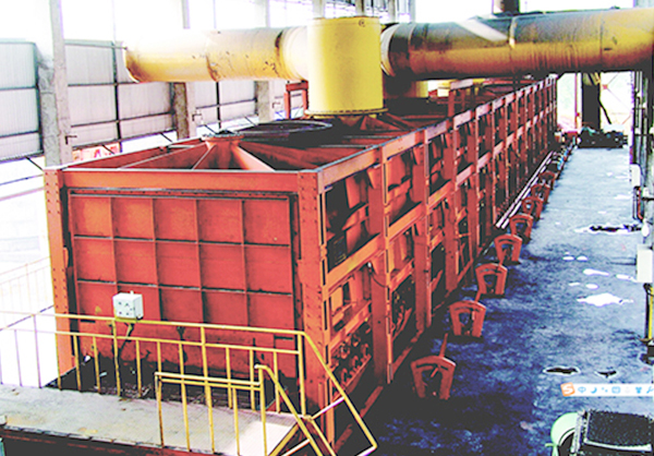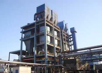
This machine is a kind of thermal equipment which can carry the pellets forward and absorb the hot air heat of HGG to realize the drying function. Because the machine is different from the normal temperature equipment, the use function of the equipment largely depends on the thermal system, operation, use and maintenance of the process.
This machine is the dehydration equipment in the production line of oxidized pellet by grate-kiln method. Its function is to dry and dehydrate φ8-φ16mm ellipsoidal ball after rolling process. The working process of travelling grate is: sieve the pressed raw ball containing the mixture of iron ore powder by screening machine, put the qualified ball into the grate for roasting, dry and preheat the ball to produce certain strength, and then send it to the rotary kiln through the kiln tail chute for roasting, so as to meet the quality requirements and produce the qualified oxidized pellet.
The wet ball with the overall dimension of φ8-φ16mm after rolling is screened by the screening machine. The qualified material ball is evenly distributed on the distribution area at the end of travelling grate by the roller distributor. With the operation of the grate bed, the pellets successively pass through drying section I, drying section II, preheating section I and preheating section II, and finally enter the rotary kiln through the shovel plate and the kiln tail chute. In the first stage of drying, the attached moisture of the ball is removed, so the temperature cannot rise very high. The second drying section is mainly to remove the crystal water from the ball, and the temperature should be controlled below the fracture temperature. Preheating section I and II is mainly to heat the ball. Its working principle is that the pellet is dried and preheated in the grate, so that the pellet has a certain compressive strength and will not be damaged during roasting in the rotary kiln. After drying, the moisture content of the pellet decreases from 8-10% to< 2%.
-
Driving device
With both sides drive adopted, the machine uses 4 nos. of VVVF motors & 2 nos. of reducers (2 sets of driving systems in total) to drive the grate bed. It has the self-locking function to prevent the grate bed from turning backward.
The synchronization of 2 nos. of transmission systems is realized by adjusting the electrical equipment, so as to ensure that the force of 2 nos. of systems is even, and 2 nos. of motors are the key to ensure the synchronization. The speed measuring device installed on the motor is used to indicate the running speed of the grate and provide speed feedback signal for the electrical control system.
Lubrication of three ring reducer: generally, it is lubricated by splashing oil in from the oil pool and cooled naturally. When the heat balance power of long-term continuous operation is insufficient, heat dissipation measures or circulating cooling lubrication shall be taken. N110-N200 medium extreme pressure gear oil is used as lubricating oil. Semi fluid grease can be used for intermittent working system. Change the lubricating oil after the new reducer runs for 300 hours, and then change it every 3000 hours. When changing oil, clean the inner wall of reducer and transmission parts.
-
Operation part
Operation part is the core of travelling grate, which is composed of head wheel, tail wheel, side seal, upper supporting wheel, lower supporting wheel, grate bed, shovel plate, side block wheel, tail tensioning device and grate pressing device.
-
Assembly of air box group
Air box group adopts double side suction type, and the air flow is extracted through the air duct. Manual butterfly valve is arranged on the air duct to control the air flow of each air box. User shall weld anchor hook on the inner surface of air box, connecting pipe and butterfly valve and apply a certain thickness of refractory material to achieve the function of heat preservation and oxidation prevention.
-
Cover body
Cover body is stepped. Due to the requirements of technology, the size of upper part of preheating section is different from that of the upper part of drying section. The two sides of the cover body are provided with a sight glass and a manhole door for maintenance. The heating of the pellet in the cover and the operation of the grate bed can be observed at any time through the sight glass, and it also serves as a sampling hole. The manhole door is mainly used for the entrance, exit and material handling of the maintenance personnel when grate bed or the inner cavity of cover body is maintained.
-
Lubrication system
Mainly for lubrication of bearings at all parts.
For the lubrication of the bearings on the head wheel, upper supporting wheel, tail wheel, tail tensioning device, lower supporting wheel and other parts of the grate, the management rules shall be prepared according to Client’s own experience, and the lubrication shall be carried out regularly.
-
Cooling water system
Water temperature shall be strictly controlled at all water-passing parts of the machine. The water supply pressure of the cooling water for head wheel axle and bearing pedestal of head wheel is 0.5 Mpa, the water supply pressure of the cooling water through the shaft of the upper supporting wheel is 0.35 Mpa, the water supply pressure of the cooling water for the water-cooled cross beam is 0.5 Mpa, and the water supply pressure of the cooling water for the support beam of the shovel plate is 0.3 Mpa. According to the water supply conditions of user's site, the water pressure of the cooling water shall be adjusted appropriately, but the temperature of the cooling water outlet shall not be higher than 40°C.
The cooling system and drainage system outside travelling grate shall be provided by design organization.
-
Electrical & control system
In the design of the machine, only the motor, reducer and mechanical transmission structure are designed, excluding the auxiliary electrical system. The electric control system protection device, interlocking signal and other equipment of traveling grate are provided by the process design. The rising or falling distance of chimney cap can be controlled by electric switch or mechanical device.
This machine is driven by two sides. Before it goes into production (including no-load commissioning & load commissioning), 2 nos. of motors must be adjusted to be synchronized to ensure the normal operation of the machine. The electrical design and installation department is in the charge of this work.
|
Item |
Drying sectionⅠ |
Drying sectionⅡ |
Preheating sectionⅠ |
Preheating sectionⅡ |
|
Nos. of air box |
2 |
3 |
2 |
6 |
|
Length of each air box (meter) |
3 |
3 |
3 |
3 |
|
Length of each chamber (meter) |
6 |
9 |
6 |
18 |
|
Area of each chamber (m2) |
16.8 |
25.2 |
16.8 |
50.4 |
Technical characteristics of equipment
|
SN |
Item |
Unit |
Value |
Remark |
|
|
1 |
Effective width of travelling grate |
m |
2.8 |
|
|
|
2 |
Effective length of travelling grate |
m |
39 |
|
|
|
3 |
Effective area of travelling grate |
m2 |
109.2 |
|
|
|
4 |
Speed range of travelling grate |
m/min |
0.59~2.9 |
|
|
|
5 |
Normal operating speed |
m/min |
1.5~2.0 |
|
|
|
6 |
Distributing thickness |
mm |
170~190 |
|
|
|
7 |
Size of pellet |
mm |
φ8-φ16 |
|
|
|
8 |
Drive (double sided drive) with one set on each side |
VVVF motor |
Model |
YTSP160L-6 |
|
|
Total power |
4×11kw |
||||
|
Voltage |
AC 380V |
||||
|
Planetary reducer |
Model |
TSHK750AH-1060 |
|
||
|
Speed ratio |
1060 |
|
|||
|
9 |
Total weight of travelling grate |
t |
~438 |
|
|
|
10 |
Dimensions (L×W×H) |
m |
47.2×7.9×9.86 |
Not including height of chimney |
|
|
11 |
Capacity |
T/h |
>90 |
|
|


 LinkedIn
 Twitter
 Facebook
 Instagram
 YouTube