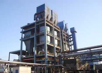
This 30㎡ blast pellet annular cooling machine (hereafter referred to as annular cooling machine) is one of the major equipment in the production of metallurgical pellets. It is used in cooling the ~1150℃ pellets discharged from rotary kilns with the particle size 5~19mm.
This 30㎡ blast pellet annular cooling machine (hereafter referred to as annular cooling machine) is one of the major equipment in the production of metallurgical pellets. It is used in cooling the ~1150℃ pellets discharged from rotary kilns with the particle size 5~19mm.
The whole machine is mainly composed of the following components: (double) transmission device, revolving body, support roll, side retaining roll, rail press, rack, feeding hopper, cover, safety equipment at discharging area, air box, discharging hopper, cover at discharging hopper, double‐layered cinder valves, and fixed sieve.
-
Transmission device
The adopted transmission mode for annular cooling machine is: electric motor—direction altering device 1‐decelerator 2‐open gear‐chain wheel‐ (pin gear). In order to reduce the forces between the parts of pin gear and components of transmission device and to stabilize the running of annular cooling machine, double transmission systems are adopted. Two sets of transmission systems simultaneously impose torque on the trolley frame, which is installed with pin gears, so that the trolley frame can start running.
-
Revolving body part
The revolving body is composed of the devices such as trolley, trolley frame, roller arms of trolley, side rail, supporting rail, chain stents, chains, and baffle of trolley.
The annular cooling machine has 28 trolleys that are casted with, which are respectively connected to the frame through two axles, rotating at the same speed of the trolley frame. The trolley baffles of welded structure are installed on the inner and outer frames of the trolley, forming a ring‐shaped container, with a sealed ring‐shaped sand sealing groove on its upper side.
One side of the roller arm of trolley is installed at the inner side of trolley frame, connecting to the axle via bonds and the other side of the roller arm is installed with rolling wheels; the rolling wheels move along the designed curves of the bottom surface of the rail press. Because the rotation of the trolley is jointly restricted by the bonds, axles, rolling arms of trolley, rolling wheels and curves of rail press, during the rotation process the trolley can turn over and reset at the designated spots.
The whole revolving frame is made of six trolley frames that are linked by high strength bolts. The trolley frames are all formed by welding steel plates together. Between the inner and outer frames are transversal triangle joint beams.
In order to stabilize the horizontal movement of the rotating part and prevent significant movement, side rails are installed under the inner trolley frames, facing the side retaining rolls installed in the racks.
Under the trolley frames are two sets of supporting steel rails, which include the inner set and outer set with the distance 2270mm, linked by high strength bolts. In addition, gasket units are used to adjust and support the horizontality of the bottom surface of the steel rail in order to guarantee the stable movement of the rotating part in the vertical direction.
Six chain stents made of 60°welding structure are linked at the outer bottom side of the trolley frame via high strength bolts. In addition, special chains (pin gears) are installed on the chain stents.
-
Support rolls
Twenty support rolls are respectively installed on the upper surface of horizontal beams of the racks. It supports the whole revolving part through supporting steel rails and is composed of roll wheels, support seats, axles, bearings, and lubricating devices. Roll wheel is the supporting and tracking apparatus of the revolving part. Also, the adjustable gasket unit is equipped between the support seat and horizontal beams of rack. Therefore, during the installation the upper support surface can be adjusted to the same horizontal level.
-
Side retaining rolls
To keep the rotating part running stably and prevent significant horizontal movement, ten side retaining rolls are respectively installed on the pillars of inside rack. It is composed of stands of side retaining rolls, side retaining rolls, roll wheels, axles, bearings, and lubricating devices. The roll wheels will restrict the horizontal movement of side rails of the rotating part. There are long holes at the connecting part of side retaining roll stands so that when installing the gap between the roll wheel and middle rail of revolving part can be adjusted. The default gap distance is set as 3.5mm. There are adjustable gasket units under the side retaining rolls, so that during the installation roll wheel and the central horizontal level of side rail can be adjusted to the same horizontal level.
-
Rail press
Rail press is made of nine straight rails and one curved rail and installed at the inner side of pillars that are at the inside of rack frames. The nine curved rails are between the ninth and tenth pile array lines at the so‐called discharging area. The function of rail press is to restrict the rotation of the trolleys through the axles and bonds connected to roll wheels and roller arms, so that the trolleys can only turn over and reset at the curve rail of dischargingarea.
-
Racks
The rack part is composed of racks, outer loop running platform, outer loop maintenance platform, and running ladders. The main part of the racks are all made of standard H steel and have total 11 upright columns(one of them supports outer loop maintenance platform)
At the centre of the racks there are four round pillars supporting a round‐shaped centre support beam, which has dual functions including central support and installation positioning thanks to its positioning graduation marks.
The outer loop running platform and the outer loop maintenance platform of the rack are connected to the ten round pillars of technical platform. All of the running platforms, maintenance platforms and ladders are all made of zinc coated steel lattice plates, which are nice‐looking and practical materials. In order to make the site work convenient to carry out, ladders are set up both inside and outside the racks, both towards the technical platforms at kiln outlet.
-
Feeding cover
Feeding hopper is composed of material hopper, air cooling wall, material retaining wall, air cooling beam, material flattening mound, and hanger frame. Feeding hopper is installed under the fixed sieve and hung on the technical platform; the two sides are respectively connected to the head cover and discharging area cover, with the hanger frame positioned and connected to the technical platform and welded on the material hopper. With the overflow device, the feeding hopper can evenly distribute the hot pellets into the trolleys and it is also a barrier to separate hot and cold zones.
-
Cover assembly
The cover is installed on the fixed welding structure component on the trolley of the cooling area. The upper part of it supports the process hanger furnace roof, and the lower part inserts into the sealed ring‐shaped sand groove of trolley barrier board of revolving part; two sides are connected to the upper column of the rack via stents with maintenance door and the two ends are respectively connected to feeding hopper and discharging cover. The cover is composed of head lower cover, head side cover, lower cover, side cover, partition wall, and stand.
-
Safety equipment at discharging area
The safety equipment at discharging area is installed on the inner loop maintenance platform at the discharging area. It is composed of upper bearings, base, springs, and electric stroke switches.
When the trolley enters the discharging area and does not turn over as required, the roll wheels on the trolley will touch the bearing slope on the safety equipment. Due to the driving force of transmission device and spring force of the safety equipment, the roll wheels on the roller arm of trolley will be forced to move along the bearing slope of safety equipment, which in turn drive the trolley to turn over. If the trolley did not turn over within the stated travel distance, the roll wheels on trolley roller arms will continue to move, then the upper bearing will press the spring and active the alarm switch, so the transmission device will stop working.
-
Air box
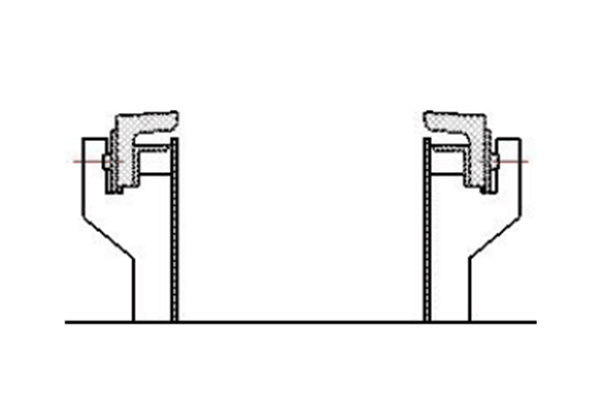
The air box part of annular cooling machine is installed or hung on the rack, and composed of nine air boxes, upper cover of air box, inclined tube of air box, nozzle of air box, sealing element of air box nozzle, dish valve, and sealing plate.
Between the air‐box part and the rotating frame adopts the sealing method of rubber friction (as shown in the picture). In the natural air the rubber components exposed outside the equipment touch the bottom surface of the trolley, making the maintenance, replacement of the sealing elements convenient, economical and practical. The sealing board can separate the air from individual air boxes to prevent air going through; in all the nozzles of air boxes two manually controlled dish valves are set up in order to adjust the amount of cooling air in the air boxes.
-
Discharge spout
The discharge spout for the trolley is installed on the horizontal beams which are located on the mid and lower frames of the ninth and tenth exterior pillar lines. It is composed of a hopper of welding structure and a rubber friction sealing element. Additionally, friction lining boards are equipped on the hopper wall and axle wheels inside the spout will facilitate the reset of the discharge trolley.
-
The covers at discharge area
The covers of discharge area are installed on the top of the trolley, with the two sides respectively connected to the feeding hopper and the cover. There are inspection doors on both inside and outside running platforms. In addition, on the tops of the cover there is also hoisting holes for checking and repairing the trolley. Inside the cover is the monitoring device, which is to check if the cooled materials are all discharged after the trolley is reset; if there are still some materials left and sticking to the surface of grid section, the monitoring device will send electric signal to inform the system control room.
-
Cinder valve
The loose materials that drop from between the grid sections during the cooling process will be collected by blast air box. These materials will then be automatically discharged through double‐layered cinder valves and then removed by workers.
Cinder valves have nozzles in the middle, dividing the cinder valves into upper and lower two layers. The cinder valves hung at the discharge outlet below the air box. Due to the heavy‐hammer effect, at certain times the two layers of valves consecutively open and shut to discharge the bulk materials; because the valve has self‐lock function, the valve boards is in sealed status for most of the time, plus bulk materials have resistance force toward airflow, this device can be sealed as well as can discharge materials.
-
Fixed sieve
The inclined fixed sieve is installed on the technical platform, vertically located between the kiln head cover of rotary kiln and the feeding hopper of the cooling machine. It is composed of sieving beam and support seat.
As during the oxidizing process of pellets in the rotary kiln ringing occurs, in order to prevent the ringing masses drop directly to the surface of trolley and destroy grid sections, 200mm gap is made on the surface of sieving body for the material to go through. The inclined design of the sieving body makes it very convenient for workers to remove the masses.
-
Others
For the convenience of production, the rotating speed of all electric motors, air temperature and pressure inside the cover, discharging condition of trolley are all equipped with inspection and monitoring device.
Wind inducing device is installed on the top of the cover, which induces the hot air to the front device and maximize the utilization of the exhaust heat.
The lubrication points of the transmission device of annular cooling machine, roll wheels of trolley roller arm, supporting rolls of the trolley all use lubrication grease. No. 1 extreme pressure lithium‐based grease is applied in winter, and No. 2 extreme pressure lithium‐based grease is applied in summer.
Specifications and processing capacity
Effective cooling area: 50㎡
Capacity for processing materials: normally 106t/h~126t/h
Material cooling
A)material type: hot pellets
B)feeding temperature: ~1150℃
C)feeding particle size: 5~19mm
D ) discharging temperature: ~150℃
E)specific gravity ofmaterial stacks: 2.2±0.1/t/m³
Pitch diameter of annular cooling machine: Φ12500mm
Number of trolleys: 28
Width of trolley: 1800mm
Thickness of material layer: <762mm
Speed of trolley:0.266~0.805m/min
Effective cooling time: 30~78min
Transmission device4
Mode of transmission: electric motor‐decelerator‐open gear‐pin gear transmission
Number of transmission devices: 2 sets
Main electric motor for transmission: A)
model of main electric motor: Y160L‐6
B)power of main electric motor: 11KW
C)rotational speed of main electric motor: 340~970r/min(frequency converter
speed regulating)
D)operating voltage of main electric motor: 415V
Main decelerator:
a)model: PVD9070
b)velocity ratio: 1:315
Open gear:
Velocity ratio: 1:4.55
1.3 Double‐layered cinder valves:
Number: 9
Mode of cinder discharge: automatic


 LinkedIn
 Twitter
 Facebook
 Instagram
 YouTube